FT-77S
Personal restoration project, a vintage model released in 1982 by the Japanese Yaesu Musen Corporation.
Upon inspection, receive was poor and there was no TX at all.
I took a look at the IF board and made some service manual adjustment for receive. And now I can copy stations.
After bringing out the scope I started poking around the IF unit and found some TX signals at the IF frequency. This signal is then fed to the RF Unit (shown below).
I then proceeded to checking out the RF Unit and found it had no TX ouput (which goes into the PA board). So I had to backtrack. I started tracing the signal from the TX IF input J1011 of the RF Unit.
Even before I started poking around the RF unit, I had a feeling that the print side of the board might need reflowing at some places, (this yaesu came out in 1982!). Rather than blindly reflowing suspect joints, I just started tracing signals with the whole RF board upside down (print side up) and hanging in mid air with all connectors plugged in. (picture below) To boost my confidence I used a alligator jumper wire to "ground" the pcb ground to the chassis. HIHI." It is fortunate that there was enough slack in the cables to be able to set up the RF board for signal tracing.
I put the radio in CW mode. As I was tracing the signal from TX IF in J11 through T22, D42, and double balance mixer, When I poked one of the terminals of the double balanced mixer, the Rx noise from the extrrnal soeaker I used became louder and instinctively I tried the PTT and found there was now some RF output. I then proceeded to reflow the solder in that area of the baord.
Some Observations. This is what you would call an "entry level" HF radio. First released in 1982, this one uses phenolic boards and no through plated holes. It has a single conversion receiver (that is why it has no 160 meters). HIHI. It has no IF shift, only one VFO (analog capacitor tuned). You could although add an external VFO (which I might do just to compare noise performance) and it does not even have an RF gain control. But it is worth investigating if one can add one (using the unused FM squelch pot concentric with the volume).
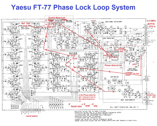
The most fascinating part of this radio is the very early PLL sytem that generates the local oscillator (bottom picture). From an engineering point of view it is uses just about the "simplest" PLL system, employing an MC4044 phase comparator with inputs from the analog VFO and a bank of crystals, one for each band (They have not thought of "divide by N frequency" counters yet, maybe). This radio does not employ large scale integration in the frequency generation system except for the frequency counter chip (essentially a BCD counter).
As such this radio is a bit of a dinosaur, but still, a fascinating study in radio technology evolution, departing enough from old vacuum tube radio technology but remaining simple enough to be "understood" without too much hair-pulling. And being easy to understand likely means easy to fix when it breaks down, if ever.
73 DU1FV


Mga Komento
Mag-post ng isang Komento